







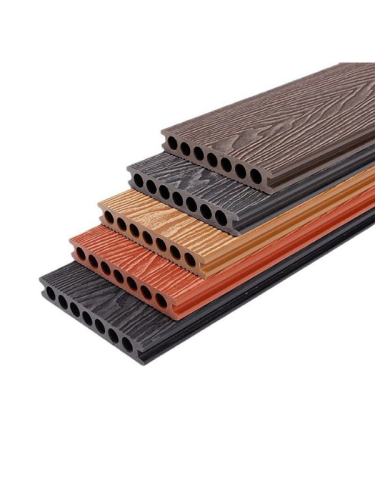
How to Install WPC Cladding on Exterior Walls
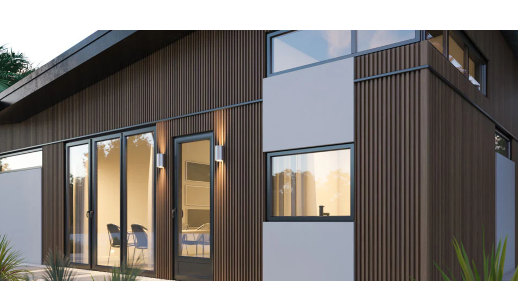
-
 By Bona
-
 30 Jul, 2026
-


Correct installation is what allows exterior WPC cladding to remain aligned, ventilated and visually consistent over time. This step-by-step guide explains how to prepare the wall, set the joists, fix the first panel, control expansion gaps and finish corners. It is intended as a practical reference for contractors, distributors and project teams working with BONA's WPC cladding range.
The dimensions below follow the supplied installation guide. Installation requirements may vary by product profile, wall substrate, climate and local code, so the final project method should always be checked against the selected model and approved construction drawings.
WPC Cladding Installation Specifications at a Glance
| Installation Point | Guide Value |
| Recommended joists | Aluminum or pressure-treated wood |
| Maximum joist spacing | 450 mm on-center |
| Anchor spacing | 500 mm |
| Lowest joist clearance above floor | Minimum 40 mm |
| Top joist clearance below ceiling | Minimum 10 mm |
| Panel clearance above ground | Minimum 10 mm |
| Recommended panel screws | Stainless steel, 4.2 × 38 mm; adapt length to joist thickness |
| Butt-joint gap | Minimum 5 mm between adjacent board ends |
| Pilot holes | Pre-drill before fastening |
Safety Equipment and Tools
Treat WPC cladding installation as construction work. Use appropriate personal protective equipment when handling, cutting and fastening panels. The supplied guide recommends gloves, respiratory protection, long sleeves, long trousers and safety glasses.
- Power saw suitable for the selected WPC profile
- Power drill and portable electric drill
- Drill bits and screw-driving tools
- Level, measuring tape and plumb bob
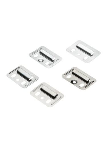
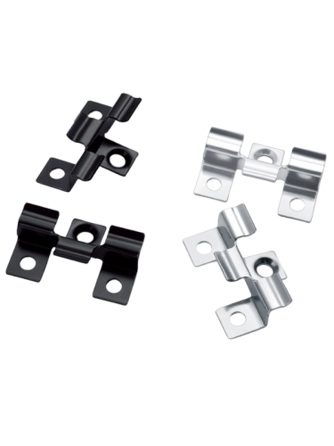
- Anchors, plastic expansion tubes and compatible screws
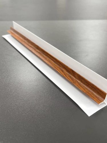
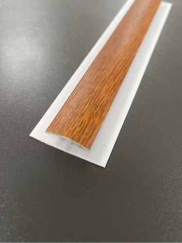
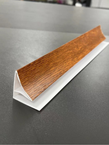
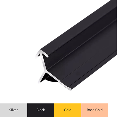
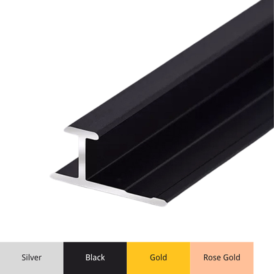
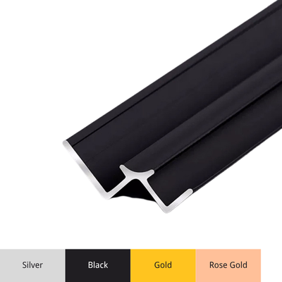
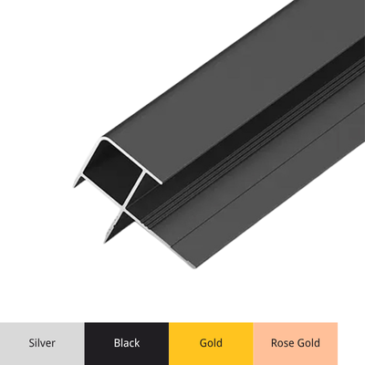
- Joists, panel trim and universal corner trim
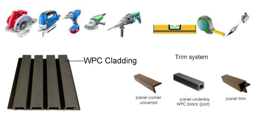
Figure 1. Safety guidance, standard tools and the principal cladding and trim components.
Before Installation: Inspect the Wall and Plan the Layout
Begin with a clean, flat and solid wall surface. Do not use the cladding as a structural member, and do not install it as a substitute for columns, support posts, beams or joists. The guide also advises against fixing the system over existing wall boards; use a code-compliant underframe instead.
Check local building requirements before work begins, because fixed exterior cladding may require permits or project-specific detailing. Prepare a board and joist layout in advance so panel widths, corner trims, openings and end joints are positioned intentionally. For available exterior profiles, review BONA's exterior wall panels before confirming quantities.
If installation is postponed, store the boards flat. Planning the board lengths before setting the joists is especially important where two boards meet end to end, because each board should be supported on its own joist at the butt seam.
Step 1: Install and Level the Joist Framework
The guide recommends aluminum joists or pressure-treated wood joists. Fix the joists securely to the wall with suitable anchors and keep the entire framework level and plumb. Irregular framing will transfer directly to the finished panel surface, so correct any high or low points before cladding begins.
- Keep joist spacing at no more than 450 mm on-center.
- Space wall anchors at approximately 500 mm.
- Leave at least 40 mm between the lowest joist and the floor.
- Leave at least 10 mm between the top of the highest joist and the ceiling.
- Provide double joists at butt joints so each panel end has independent support.
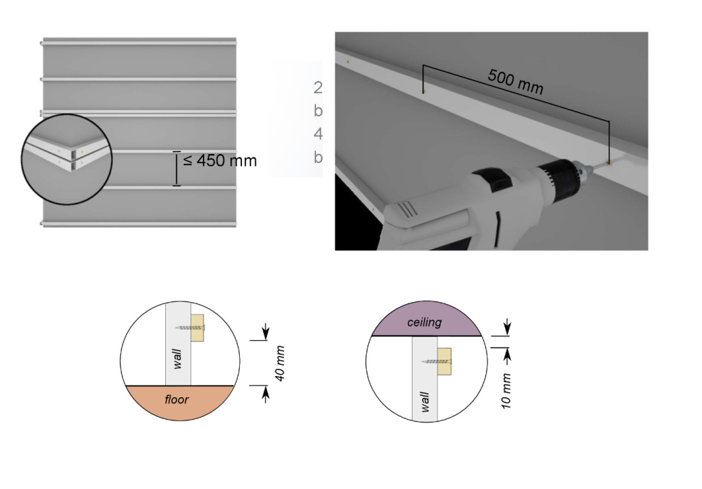
Figure 2. Joist layout, anchor spacing and required clearances at the floor and ceiling.
Step 2: Set the Starting Trim and First Panel
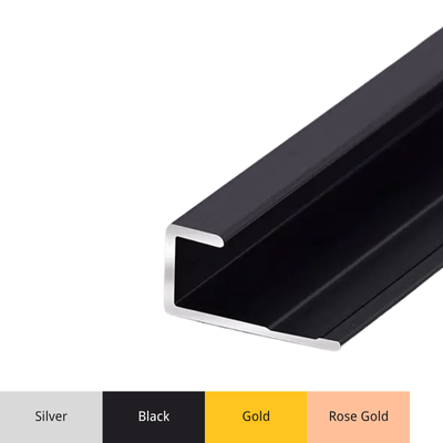
Decide the installation direction and fit the appropriate starting detail. Depending on the edge condition, the first panel can begin against a universal L-shaped corner profile or a panel trim. Set the first panel carefully because its alignment controls the line of every panel that follows.
Maintain at least 10 mm between the bottom of the cladding and the ground. This opening supports ventilation and leaves room for normal expansion and contraction.
Step 3: Pre-Drill and Fasten Through the Screw Groove
Always pre-drill a pilot hole before installing the screw. The screw should pass through the designated groove of the cladding rather than through the visible face. Avoid overtightening: the fixing must hold the panel securely without crushing or deforming the profile.
The supplied guide recommends 4.2 × 38 mm stainless-steel screws for panel fastening. The final screw length must be adapted to the joist thickness and the approved substrate connection.
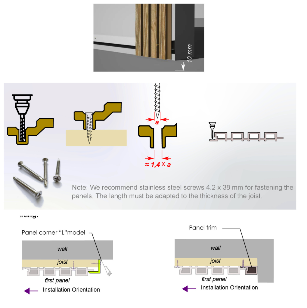
Figure 3. First-panel positioning, 10 mm ground clearance, pilot-hole drilling and screw placement.
Step 4: Connect and Secure the Remaining Panels
Engage the second panel with the first, check that the joint is fully seated, and fasten the new panel to each joist through its screw groove. Continue across the wall using the same sequence: connect, align, check with a level and fasten.
- Check the panel line regularly instead of waiting until the full wall is covered.
- Keep screws consistently positioned inside the fixing groove.
- Do not force panels together if the joint is obstructed or the joist frame is out of alignment.
- Keep the ventilation opening at the bottom unobstructed.
Step 5: Control Butt Joints and Board Ends
Where two cladding boards meet end to end, leave a minimum 5 mm gap. The joint should be positioned over the planned double-joist support so each board end can be fixed independently. The gap provides ventilation and movement space and helps reduce stress at the joint.
Avoid placing several butt joints in one visually obvious line unless the elevation design specifically calls for it. A planned staggered layout normally produces a cleaner finished façade.
Step 6: Finish Inner and Outer Corners
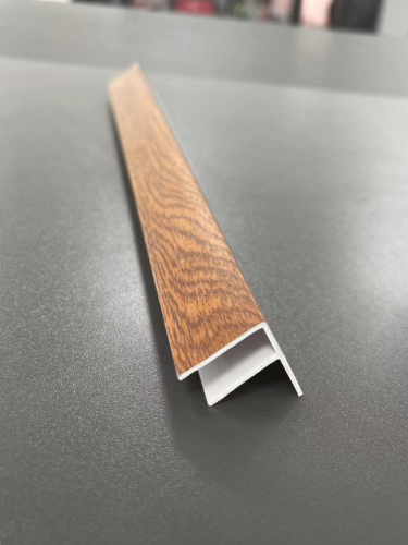
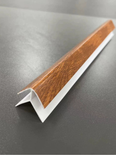
For an inner corner, cut the final cladding board to the required width and fasten it to the joist using color-matched screws where specified. For an outer corner, install the universal L-shaped panel corner vertically and fasten it through the cladding boards with color-head screws.
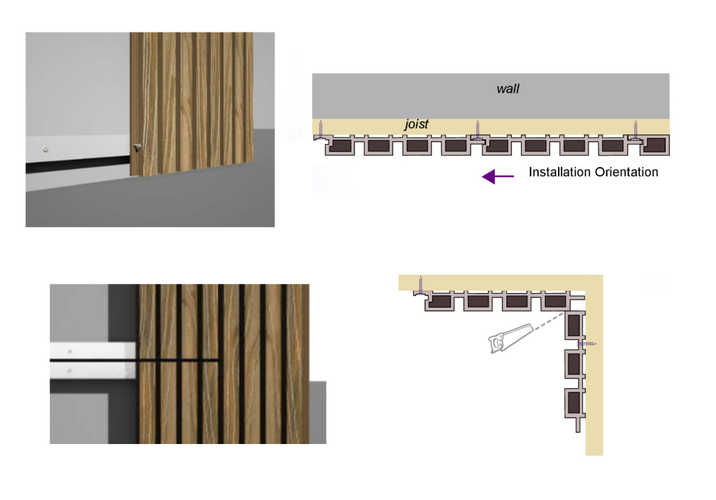
Figure 4. Repeating panel installation, minimum butt-joint gap and inner-corner finishing.
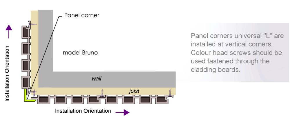
Figure 5. Universal L-shaped corner trim installed vertically at an outside corner.
Final Inspection Checklist
- The joist framework is level, plumb and securely anchored.
- Joist spacing does not exceed 450 mm on-center.
- Anchor spacing follows the 500 mm guide value.
- The lowest joist and top joist retain their specified clearances.
- The cladding remains at least 10 mm above the ground.
- All screw locations were pre-drilled and fixed through the screw grooves.
- Butt joints have at least 5 mm movement and ventilation space.
- Panel ends are supported independently at double joists.
- Corner trims are straight, secure and visually consistent.
- Ventilation openings are not blocked by sealant, soil, paving or debris.
Common WPC Cladding Installation Mistakes
Installing over an uneven wall: An uneven substrate creates a distorted joist plane and visible waves across the finished cladding.
Using excessive joist spacing: Wide unsupported spans can reduce panel stability. Follow the maximum 450 mm spacing in the supplied guide unless a model-specific document states otherwise.
Skipping pilot holes: Driving screws directly into the profile can split, deform or damage the fixing groove.
Closing every gap tightly: WPC panels need ventilation and movement space. Preserve the specified ground, ceiling and butt-joint clearances.
Supporting both board ends on one narrow joist: Use double joists at butt seams so each board end has a reliable fixing area.
Treating cladding as structural: The panels are a finish system, not a substitute for load-bearing framing.
Choosing a BONA Exterior WPC Cladding Profile
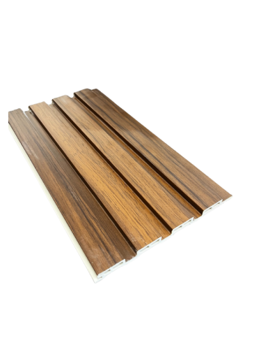
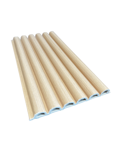
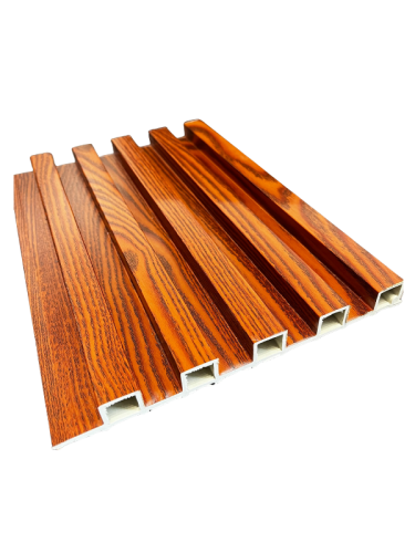
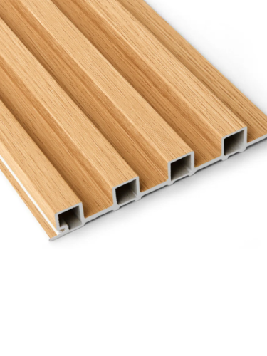
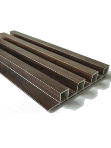
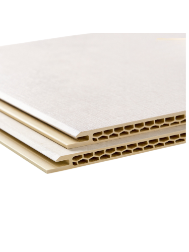
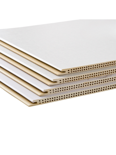
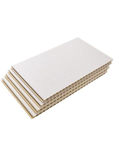
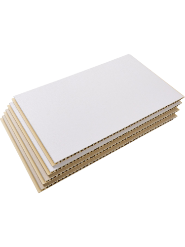
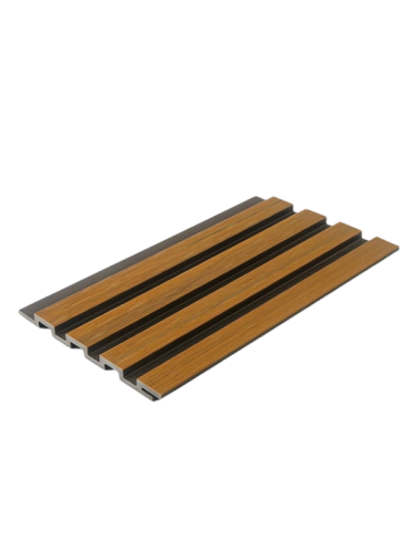
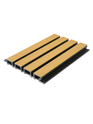
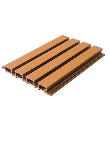
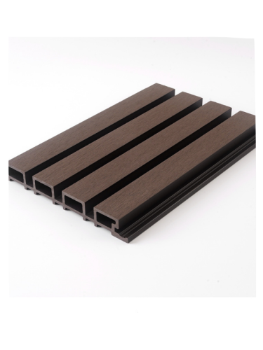
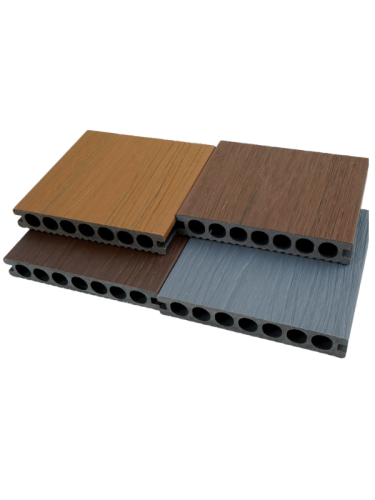
Installation planning should begin with the actual panel profile. BONA's WPC-X01 hollow cladding panels use a lightweight multi-cavity structure, while WPC-S01 co-extrusion cladding panels add a protective co-extruded surface for projects that prioritize stain, scratch and fade resistance. Confirm panel dimensions, matching trims, packing quantities and model-specific installation details before the order is finalized.
Frequently Asked Questions
What is the maximum joist spacing for WPC cladding?
The supplied guide specifies a maximum spacing of 450 mm on-center. A selected product or engineered project may require a different spacing, so confirm the model-specific document before installation.
How far apart should the wall anchors be?
The guide shows anchors spaced at 500 mm along the joists.
How much clearance should be left below WPC cladding?
Leave at least 10 mm between the cladding and the ground. The lowest joist should also remain at least 40 mm above the floor.
What screws should be used for WPC wall cladding?
The guide recommends stainless-steel screws measuring 4.2 × 38 mm, with the final length adapted to the joist thickness.
Do WPC cladding panels need expansion gaps?
Yes. The guide calls for at least 5 mm at butt joints, 10 mm above the ground and appropriate clearances around the joist framework to support ventilation and normal material movement.
Can WPC cladding be installed directly over existing wall boards?
The supplied guide advises against installing over existing wall boards. Use a clean, solid substrate and a code-compliant joist or underframe system.
Is WPC cladding structural?
No. It should not be used as a column, support post, beam, joist or other load-bearing element.
Plan the Product and Installation System Together
A reliable exterior wall system depends on the panel, joists, fasteners, trims and site details working together. Browse BONA's WPC cladding range, read the related comparison of PVC vs WPC vs SPC wall panels, or contact BONA to discuss panel profiles, colors, samples, quantities and technical documentation for your market.
-
PVC vs WPC vs SPC Wall Panels: Which One Wins for Your Project?
09 Jun, 2026
-

WPC Decking Maintenance Tips: A Practical Care Guide for Long-Lasting Outdoor Decks
09 Jun, 2026
-
UV Marble Sheet Buying Guide: How to Source the Right Panels in 2026
09 Jun, 2026
-
UV Marble Panels in Hotel Lobbies: 5 Real Projects That Replaced Real Stone
09 Jun, 2026